")
")
")

")
Multi-source networks under FPI control
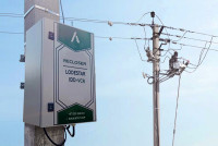
Distributed generation requires not only reliable equipment but also flexible approaches to installation and monitoring. A further confirmation of this came with the installation of fault passage indicators (FPIs) in non-standard network configurations in Jordan.
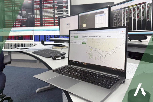
The key feature of this project is the multi-source network configuration in the city of Irbid. The installed FPIs operate on lines with distributed generation: power is supplied to consumers both centrally — from the IDECO distribution network — and from alternative sources, specifically from JEPCO solar power plants.
To accurately track line dynamics and equipment status, the FPIs were connected to the KOMORSAN monitoring and diagnostics system. As a result, our technical support engineers receive real-time comprehensive information on device performance. Partners, in turn, are provided with detailed line load analytics throughout the day.
This project represents another step forward in our efforts to deepen expertise in non-standard grid solutions and expand our international presence.
Faulty section identification in overhead lines explained
How faulty section identification works in distribution networks
Every power outage has a clock running from the moment it starts. The longer crews spend searching for the fault location on an overhead line, the longer customers stay in the dark — and the higher the cost to the utility. Faulty section identification is the process that cuts that search time down from hours to minutes, and modern fault indicator technology is what makes it possible at scale.
Why "Finding the Fault" is harder than it sounds
A medium-voltage distribution feeder can stretch for tens of kilometers, branching into multiple laterals along the way. When a short-circuit or earth fault occurs somewhere on that network, the circuit breaker or recloser at the substation trips — but it gives operators almost no information about where the fault is. All they know is that something is wrong somewhere downstream.
Traditionally, repair crews would drive the entire feeder route, visually inspecting poles and conductors until they found the problem. On a long rural feeder with multiple branches, that could easily take two to four hours. During that time, all customers on the affected segment — and often on healthy segments that were unnecessarily de-energized — remained without power.
Faulty section identification changes the logic entirely. Instead of searching for the fault after it happens, the system already knows which section contains it.
The role of fault indicators
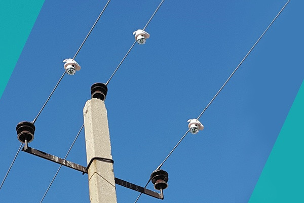
Fault indicators (also called fault passage indicators, or FPIs) are devices mounted directly on overhead line conductors or at pole locations throughout the feeder. Their job is to detect the passage of fault current — whether from a short circuit between phases, or from a single-phase earth fault — and to signal that the fault passed through their location.
When a fault occurs, every fault indicator between the substation and the fault point "sees" the fault current and triggers its flag. The indicators beyond the fault point do not — because no fault current flowed past them. This pattern of tripped and non-tripped indicators immediately narrows the fault location to a specific line section: the segment between the last indicator that tripped and the first one that did not.
That is the core principle of faulty section identification based on fault indicators, and it is both elegant and practical.
From simple flags to smart network data
Early fault indicators relied on a physical flag — a visible mechanical indicator that crews could spot while driving the line. That alone was a significant improvement, but it still required a visual patrol of the entire feeder to check the status of each flag.
Modern fault indicator systems go much further. Each indicator communicates its status — tripped or not tripped — to a central control system via a wireless communication unit. The control center receives this data within seconds of the fault, and the fault management software automatically identifies the faulty section based on the pattern of received fault flags.
The analysis also takes into account:
- The topology of the distribution network — which sections connect to which, and how feeders branch into laterals
- Pre-fault and post-fault current measurements from the indicators, which help distinguish between a genuine fault and a transient event
- Circuit breaker and recloser statuses, which confirm which parts of the network were isolated and when
- Feeder and lateral loading data, which helps validate fault scenarios in networks with distributed generation
Together, these inputs allow the system to pinpoint the faulty section with high confidence, even in complex radial or meshed network configurations.
Short-circuit faults vs. earth faults: different problems, same solution
Not all faults are the same, and faulty section identification must handle both major fault types.
Short-circuit faults occur when two or three phases come into contact — through a fallen conductor, a damaged insulator, or contact with a tree. These faults produce very high currents that are relatively easy to detect.
Earth faults (single-phase-to-ground faults) are more common in medium-voltage networks but significantly harder to detect. In networks with an isolated or compensated neutral (Petersen coil), the earth fault current can be very small — sometimes just a few amperes. The fault may persist for hours without triggering a line trip, all while creating a dangerous touch voltage risk at the fault point.
Modern short-circuit and earth fault indicators are designed to detect both fault types. For earth faults, they use specific detection methods — transient analysis, directional measurement of zero-sequence current — to reliably identify which section contains the fault even when the fault current is low. This is critical, because without proper earth fault section identification, network operators either ignore the fault (which is dangerous) or de-energize large sections of the network to find it (which is costly).
Integrating faulty section identification into grid operations
Faulty section identification does not work in isolation — its real value comes from how it integrates into the wider grid control environment.
When the fault location data reaches the SCADA or fault management software, operators can immediately dispatch repair crews to the right place. But with automation, the system can go further: it can automatically open the sectionalizing switches that isolate only the faulty section, then restore power to all healthy segments. This is the logic behind FLISR — Fault Location, Isolation, and Service Restoration — which reduces outage duration for unaffected customers from minutes to seconds.
For utilities working toward Smart Grid compliance or improving their SAIDI/SAIFI reliability metrics, this kind of automated fault section identification is not a luxury — it is a fundamental building block.
What good faulty section identification looks like in practice
A well-implemented fault identification system has a few defining characteristics:
Speed. The control center should have fault flag data within seconds of the fault occurring, not after a crew patrol that takes hours.
Accuracy. The system should correctly identify the faulty section even in the presence of missed or incorrect indicator readings — which can happen due to communication errors or abnormal fault conditions. Redundant logic and current measurement data help here.
Coverage. Indicators need to be deployed at appropriate intervals along the feeder, including on laterals. A gap in coverage is a gap in identification capability.
Reliability in harsh conditions. Overhead line equipment operates in rain, ice, extreme heat, and high wind. Fault indicators must maintain their detection and communication functions throughout.
Integration. The fault flag data should flow directly into the utility's existing SCADA or DMS (Distribution Management System), not sit in a separate silo.
When these elements come together, faulty section identification becomes a routine, automatic part of grid operations — something the control center knows within a minute of any fault, without anyone driving a single kilometer of feeder.
The bottom line
Faulty section identification is one of the most impactful improvements a distribution utility can make to its operations. It directly reduces outage duration, cuts crew patrol costs, improves safety by quickly pinpointing dangerous fault locations, and provides the data foundation for network automation.
The technology to do this — overhead line fault indicators with communication capability, combined with software that maps fault flag patterns to the network topology — is mature, proven, and deployable on existing overhead lines without major infrastructure changes.
For utilities still relying on manual patrols to find fault locations, the question is not whether to implement faulty section identification, but how soon.
Frequently Asked Questions
What is faulty section identification in a power distribution network?
Is the process of automatically determining which specific segment of an overhead or cable distribution line contains a fault — such as a short circuit or earth fault — immediately after it occurs. Rather than sending crews to patrol the entire feeder, the system uses fault indicators installed along the line to pinpoint the affected section within seconds.
How do fault passage indicators help locate a fault on an overhead line?
When a fault occurs, every indicator between the substation and the fault point detects the fault current and triggers its flag — while indicators beyond the fault point show no response. That boundary marks the faulty section. In modern systems, this information is transmitted wirelessly to the control center in real time, so operators know the fault location without any physical patrol of the line.
Can fault indicators detect earth faults, not just short circuits?
Yes. Modern fault indicators are designed to detect both short-circuit faults and earth faults, including high-resistance earth faults in networks with an isolated or compensated neutral. Earth fault detection typically relies on transient analysis or directional measurement of zero-sequence current, since earth fault currents can be very low — sometimes just a few amperes — and standard overcurrent detection alone is not sufficient.
What is the difference between fault location and faulty section identification?
Fault location typically refers to calculating the precise distance to the fault point — often in meters or kilometers from the substation — using impedance-based or travelling-wave methods. Faulty section identification is a broader, more practical concept: it narrows the fault down to a specific line section between two known points, such as two consecutive fault indicators or switching devices. For most field operations, knowing the faulty section is sufficient to dispatch crews directly to the fault area.
How does FLISR relate to faulty section identification?
FLISR — Fault Location, Isolation, and Service Restoration — is an automation workflow that builds directly on faulty section identification. Once the system identifies the faulty section, FLISR automatically sends switching commands to isolate only that segment, then reconfigures the network to restore power to all healthy sections. The result is that customers outside the faulty section experience a brief interruption lasting only seconds rather than a prolonged outage.
The IDD-CB Load Break Switch: A New Level of Distribution Network Reliability
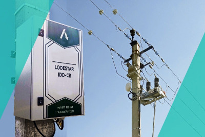
With rising energy consumption and increasing demands on power supply reliability, grid companies are facing the urgent need to modernize their equipment. Traditional methods of sectioning and protecting power lines often fail to promptly respond to incidents and minimize damage to consumers. A key solution to this problem is the implementation of digital control devices, such as the IDD-CB load switch developed by ATRIY.
This device is designed for remote sectioning of overhead lines (OHL) and fundamentally changes the approach to network management. A load break switch creates a visible gap in the circuit between equipment that has been taken out for repair and equipment that is under operational voltage.
Why is the IDD-CB important for energy companies?
Minimizing consumer outages
The fundamental mission of any utility company is to provide an uninterrupted supply of energy to its residential and commercial customers. The IDD-CB, when combined with the Automatic Network Restoration System (FLISR), allows for selective identification of the faulty section of a power line. Instead of de-energizing an entire district or community, the device automatically disconnects only the faulty section, maintaining power to the rest of the network.
Reduced Troubleshooting and Repair Time
The equipment can accurately detect the direction and type of fault (including difficult-to-diagnose single-phase-to-ground faults). This reduces fault location time by more than eightfold. Repair crews no longer spend hours patrolling the lines; they can now be dispatched directly to the location of the fault.
Creating a "Visible Break" and Safety
The unique design of the IDD-CB combines a vacuum circuit breaker and a disconnector. When a line is taken out of service for repair, the device creates a reliable, visible break in the circuit. This is critical for the safety of crews working on-site, eliminating the risk of erroneous power supply.
Installing IDD-CB digital load break switch is more than simply replacing outdated equipment. It represents a transition to a new technological paradigm, where the main criteria are reliability, safety, and cost-effectiveness through reduced network downtime and optimized maintenance services. For energy companies striving to improve service quality and reduce operating costs, such devices are becoming a necessity, not a luxury.
We invite you to The Middle East Energy 2026

Dear partners!
We invite you to our booth H5.A70, where we will present our new products as well as proven digital and complex solutions for Energy industry:
- equipment for monitoring and diagnosing overhead lines, including Fault Passage Indicators powered from the line and sensitivity to emergency currents from 0.2 A;
- advanced solution for fault detection Lodestar CL0.5 BM-S for registering of faults is based on special intelligent algorithm, that makes possible to detect PtG fault and its direction from 0.5A;
- short-circuit and earth fault Indicator Lodestar PT2-PRO intended for detection of fault localization in overhead and cable power distribution lines of 6-35 kV;
- updated line of Lodestar FM feeder monitors for quick accident search an separation of damaged part of the power line;
- software solutions for overhead and cable line monitoring and control.
You will have the opportunity to explore the System of Automatic Network Recovery (FLISR) on the basis of Intellectual Disconnector IDD, fault passage indicators and hardware-software complex KOMORSAN.
About the event:
For 50 years, Middle East Energy connects qualified buyers with proven suppliers to move real projects forward. Discover what’s new in energy, learn from proven experts, and network with trusted suppliers.
Celebrating its 50th edition, Middle East Energy will unite 1,900 exhibitors, five high-impact conferences, five dedicated product sectors, and an exclusive VIP programme - all under one roof. Join 45,000+ energy professionals from 07 - 09 April 2026 at Dubai World Trade Centre, UAE.
Let’s plan our meeting at your convenient time.
Date: 07-09.04.2026
Venue: Dubai World Trade Centre, Dubai, UAE
ATRIY Integrated Solution: Building a Highly Automated Power Distribution System
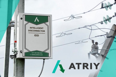
ATRIY presents a comprehensive solution for managing 6-70 kV overhead lines based on the Intelligent disconnector IDD, the Lodestar CL0.2B VEH short-circuit indicators, and the Komorsan hardware and software system with the FLISR module.
This overhead line management system radically changes the approach to troubleshooting line faults, transforming a simple sectioning device into a fully-fledged line diagnostician. The key objective of this equipment is to minimize fault location time, especially in challenging weather conditions. There is no need for long-distance route in freezing temperatures or inclement weather.
Discover the seven unique technical advantages of this system — complementing its already extensive list of benefits — to help you make the right choice:
- High sensitivity. Detects fault currents as low as 0.2 A, making it 50 times more sensitive than many similar systems.
- Detects even hidden insulation faults.
- Precise fault location navigation shows whether the fault is located before or after the FPI installation point.
- Intelligent selectivity. When integrated with the Komorsan-based SACS module, the system disconnects only the section closest to the fault, effectively minimizing the blackout zone.
- Personnel safety. The built-in live operation interlock eliminates the risk of accidental switching, ensuring safe and error-free operation.
- In-depth analysis. Equipped with non-volatile memory, the device stores up to 20,000 fault events, preserving complete waveforms for thorough post-event analysis and the implementation of preventative strategies.
- Powered by line voltage, the device is maintenance-free and does not require periodic battery replacement.
This is more than just equipment; it is a strategic solution. By integrating the IDD, Lodestar CL0.2B VEH, and the Komorsan system, it automates distribution networks and lays the groundwork for a robust and reliable energy future.
AI and Machine Learning in Grid Fault Detection & Location

Revolutionizing Grid Fault Detection and Location with AI and Machine Learning
In today’s rapidly evolving energy landscape, detecting and locating faults in power grids efficiently and accurately is crucial. Grid faults—electrical malfunctions in the grid—can lead to power outages, safety hazards, and substantial economic losses. However, thanks to cutting-edge advancements in artificial intelligence (AI) and machine learning (ML), these challenges are being addressed in innovative ways.
What is Grid Fault Detection & Location?
Grid fault detection and location involve identifying faults within a power network and pinpointing the exact location of the issue. Faults can include short circuits, equipment failures, or other anomalies that interrupt the flow of electricity. Detecting these problems quickly is essential to restore power, prevent further damage, and maintain the overall efficiency of the grid.
Why is Traditional Fault Detection Challenging?
Traditional methods of fault detection in electrical grids often rely on manual inspections, sensor data, or simple detection algorithms. While these methods can be effective, they are time-consuming and sometimes inaccurate, especially in large, complex power grids. This delay can lead to prolonged outages, higher operational costs, and a loss of customer trust.
AI and Machine Learning: The Game Changers
The integration of AI and machine learning technologies into fault detection has transformed this field. These advanced algorithms can process vast amounts of data from smart sensors and grid systems in real time. By using historical data, environmental conditions, and system behavior, AI-powered systems can not only detect faults more quickly but also predict where they are likely to occur.
How Does AI Improve Fault Detection?
AI improves fault detection by analyzing patterns in the grid’s behavior. For example, machine learning models can identify deviations in voltage, frequency, and other key indicators that might signal a fault. Once a fault is detected, these models use data from surrounding sensors to pinpoint its exact location, enabling faster resolution. AI systems can even classify the type of fault, helping engineers address the problem more effectively.
Real-Time Monitoring with Smart Grids
One of the key benefits of using AI in grid fault detection is the ability to monitor grids in real time. Smart grid systems, equipped with advanced sensors, generate a constant stream of data. This data can be processed by AI algorithms to detect anomalies that could indicate faults long before they lead to outages. These systems not only reduce the time it takes to detect faults but also improve the accuracy of their location, significantly reducing downtime.
The Role of Machine Learning in Fault Location
Machine learning (ML), a subset of AI, is particularly powerful when it comes to fault location. By training algorithms on large datasets, ML models can make sense of complex relationships between different grid variables. When a fault occurs, the system compares real-time data with historical patterns to identify the fault’s location and predict its impact on the rest of the grid.
This level of predictive insight is a game changer, as it allows grid operators to perform preventative maintenance, reduce the risk of widespread outages, and improve the overall resilience of the grid.
Key Benefits of AI-Driven Fault Detection and Location
- Faster Detection and Response: AI-powered systems can detect faults in seconds, significantly reducing response times and the duration of outages.
- Increased Accuracy: Machine learning algorithms can pinpoint the exact location of a fault, eliminating guesswork and manual labor associated with traditional methods.
- Predictive Maintenance: AI systems can predict where faults are likely to occur, allowing for proactive maintenance and reducing the likelihood of system failures.
- Cost Efficiency: By minimizing downtime and improving fault resolution times, AI-powered systems save money on maintenance and repair costs.
- Improved Grid Reliability: Real-time monitoring and fault detection ensure that the grid is operating at optimal efficiency, reducing the risk of widespread outages and improving customer satisfaction.
The Future of Grid Fault Detection
As AI and machine learning continue to evolve, we can expect even more breakthroughs in grid fault detection and location. The use of deep learning models and advanced sensor networks will make it possible to detect and locate faults with unprecedented accuracy, ensuring the continuous operation of our electrical grids.
Moreover, as smart grids become more widespread, the integration of real-time fault detection will allow for even more automated and reliable grid management, contributing to the overall sustainability of energy systems.
Conclusion
Grid fault detection and location are critical components of maintaining a reliable and efficient power grid. With the advent of AI and machine learning technologies, these tasks are becoming faster, more accurate, and cost-effective. As the energy sector continues to embrace these advancements, grid operators can look forward to enhanced resilience, improved performance, and a more reliable power supply for consumers.
Rapid Fault Detection and Localization: A Key to Network Reliability
The expansion of networks, digitalization, and stricter regulations have made fault detection and localization a top priority for energy companies. Outages directly hurt financial metrics and customer satisfaction.
Modern, complex medium-voltage grids require solutions that go beyond traditional maintenance. Rapid fault pinpointing is now a critical operational task.
A key challenge lies with overhead lines (OHL), vulnerable to weather. To address this, Atriy offers the OHL Fault Indicator Lodestar CL0.5 BM-S. This device accurately determines fault area on 6-70 kV lines and transfers information to the operator. With easy, calibration-free setup, it is designed to work in isolated or compensated neutral networks.
By implementing targeted solutions like this, grid operators can drastically cut fault-finding time on critical assets. This transforms their approach from reactive response to proactive network management—a critical step toward building resilient and efficient power systems.
Merry Christmas and a Happy New Year!

Dear Partners,
On behalf of the entire team at ATRIY company, we extend our warmest wishes to you and your colleagues for a joyous Christmas and a prosperous New Year.
We truly value our partnership and look back with gratitude on the success we have achieved together in the past year. We are excited about the opportunities that the coming year holds and we are confident that our collaboration will continue to flourish in the coming year.
May the holiday season bring you peace, happiness, and time to spend with your loved ones. We wish you a wonderful celebration and a fantastic start to the New Year.
Warm regards,
ATRIY team
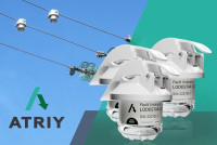
ATRIY Introduces IDD-VCR Vacuum Recloser to Enhance Network Reliability
ATRIY launches a new product — the IDD-VCR Vacuum Recloser, designed for automatic sectioning and backup in networks with multiple power sources. The device enhances the reliability of consumer power supply and efficiently manages medium-voltage distribution networks.
Key Features:
- Operates in any network topology (radial, ring, with dual supply) without reconfiguration.
- Performs relay protection (ANSI-50/51) and automation functions, including auto-reclosing (AR).
- Equipped with an intelligent control system and supports IEC 61850 and IEC 60870-5-104 protocols.
- Ensures rapid power restoration after outages.
Advantages: high reliability, visible circuit break, minimal maintenance, and reduced downtime.
The IDD-VCR is ideal for network modernization projects, industrial facilities, and utility infrastructure.
Contact us for a consultation or to place an order.
ATRIY in the Philippines: Powering Reliability in the Tropics

ATRIY LLC рparticipates in the 50th Annual National Convention (ANC) and the 3E XPO 2025, held at in Philippines. Hosted by the Institute of Integrated Electrical Engineers of the Philippines, Inc. (IIEE), this landmark "Golden Year" event is the premier gathering for professionals in the electrical, electronics, and energy engineering sectors.
At the exhibition, ATRIY's innovative devices are being featured at the booth of our partner company, CENTRADE. For more than five years, they have been purchasing our equipment for the Philippine power grid, as they believe that our devices can reliably operate in high humidity and strong winds, helping power grid operators identify damaged sections of the grid in real-time.
Our specialists are on site demonstrating the company's flagship products: the Lodestar CL0.5B and Lodestar CL0.5 BM series Fault Passage Indicators. These top-of-the-range solutions are designed for the rapid detection of fault location and direction on overhead power lines.
The significant interest and positive reception from exhibition visitors towards our products are a tremendous reward for our team. Such feedback strengthens our commitment to the strategic goal: ensuring the highest level of power supply reliability worldwide.
More...
Understanding ground fault indicators - how ground fault monitoring works
In any modern industrial or commercial facility, the safety and reliability of the electrical network are paramount. An unexpected interruption in the power supply can halt production, while an undetected electrical fault can lead to catastrophic equipment damage, fires, and severe safety hazards. One of the most common and dangerous types of faults is a ground fault. To combat this risk, specialized safety devices known as ground fault indicators are essential. These devices serve as the first line of defense, providing early warnings of potentially hazardous conditions long before they escalate, ensuring the entire installation remains stable, safe, and productive.
How Ground Fault Indicators Detect Faults
The fundamental principle behind ground fault indicators is the constant monitoring of current balance within an electrical circuit. In a properly functioning, healthy grounded system, the current flowing from the source to the load through the phase conductors is exactly equal to the current returning. There should be zero current leakage to the ground. However, when a ground fault occurs—often due to deteriorating insulation, moisture, or accidental contact—a portion of the current escapes its intended path and flows directly to the ground. This creates a dangerous imbalance in the circuit.
This is precisely what ground fault indicators are designed to detect. Using highly sensitive current sensors, known as Core Balance Current Transformers (CBCT) or toroidal transformers, which enclose the phase and neutral conductors, the device continuously measures the vector sum of the currents. When this imbalance exceeds a predetermined, safe threshold, the indicator immediately triggers an alarm. For personnel safety, this threshold is often as low as 5-30 mA. For equipment protection, where the goal is to prevent damage from sustained, low-level arcing faults, the sensitivity might be set higher (e.g., 100-500 mA). This alarm is typically a visual signal, like a flashing red light, or an output relay that can be connected to a larger control system, alerting personnel that a specific part of the electrical infrastructure requires immediate attention. These advanced products are critical for maintaining the health of any power system.
Types of Ground Fault Indicators and Their Applications
Not all solutions are created equal. The right choice depends on whether the priority is protecting people, protecting equipment, ensuring continuity, or locating the fault.
Type AC / Type A (RCD/GFCI — high sensitivity for people):
Used for personnel safety on relevant low-voltage circuits. They disconnect rapidly at low residual currents (see values above) to mitigate the risk of electric shock in workshops, laboratories, and areas with frequent human–equipment interaction.
Adjustable, time-delayed protection for selectivity (Type S RCD / GFPE):
In complex industrial settings, continuity of service and selective tripping are critical. Time-delayed/selective devices let engineers coordinate sensitivity and intentional delay (typically tens to hundreds of milliseconds for selective RCDs; higher-amp settings for GFPE on services/feeders) so harmless transients (e.g., motor inrush) don’t cause upstream trips, while sustained faults are cleared in the correct location.
Panel-mounted monitors (RCM):
Residual current monitors display or transmit real-time leakage values. Trending a slowly increasing residual on a critical motor is a classic early sign of insulation degradation—ideal for predictive maintenance. RCMs provide signaling but do not perform automatic disconnection.
RCMs provide signaling but do not perform automatic disconnection.
Fault Passage Indicators (FPI/FCI) for feeders (MV):
When the task is to find where the fault occurred on medium-voltage feeders, use ground fault indicators designed for MV networks—fault passage indicators. For example, the Lodestar PT2 helps quickly localize earth faults/short circuits along 6–35 kV overhead and cable lines, cutting patrol time and speeding restoration.
Key Benefits of a Robust Ground Fault Monitoring System
Integrating a network of appropriate ground fault indicators offers tangible returns through improved uptime and asset preservation. The primary advantages include:
- Enhanced Safety: By providing immediate alerts for hazardous ground faults, these indicators significantly reduce the risk of electric shock and fire. This offers superior safeguarding for personnel and the facility itself, which is always a high priority.
- Maximized Operational Uptime: In a continuous process environment, an unexpected shutdown is incredibly costly. Ground fault indicators allow a system to alarm without necessarily tripping, giving staff the chance to conduct an orderly shutdown or address the issue before a critical failure occurs, thus keeping the power flowing.
- Prevention of Costly Equipment Damage: An undetected, persistent ground fault can cause severe damage to motors and transformers. The early warning provided by ground fault indicators helps prevent this, avoiding expensive repairs and replacement costs.
- Simplified and Rapid Troubleshooting: When a fault occurs in a large industrial system, finding its location can be a time-consuming challenge. Consider a large manufacturing plant with dozens of machine lines. Without zoned monitoring, a ground fault could shut down the entire facility while electricians spend hours testing each circuit. With indicators on each feeder, an alarm instantly points to "Line 3, Stamping Press," reducing downtime from hours to minutes. This targeted approach is a cornerstone of an efficient maintenance system.
- Proactive Maintenance: A recurring fault alarm on a particular feeder can indicate deteriorating insulation or an aging piece of equipment, allowing maintenance to be scheduled proactively. This is vital in managing the lifecycle of high-voltage equipment. A low resistance path to ground during a fault is what can cause significant damage.
Debunking Common Myths
Misconceptions can lead to inadequate safety measures. Let's address some common myths about ground fault indicators.
- Myth 1: "They cause nuisance tripping." Reality: This is only true for incorrectly specified devices. Modern, adjustable products (like Type S relays) with configurable time delays can easily distinguish between a dangerous ground fault and a temporary inrush current from a motor, virtually eliminating false alarms.
- Myth 2: "A standard circuit breaker is enough." Reality: A standard breaker is designed to protect against overloads and short circuits (often hundreds of amps). It is completely blind to the low-level leakage currents (as low as 50 mA) that can be fatal to humans and cause fires. Relying solely on a breaker for ground fault protection is a dangerous oversight.
- Myth 3: "They are only for high-voltage systems." Reality: The risk of lethal electric shock is actually highest in common low-voltage (e.g., 230/400V) systems, where personnel are most likely to be working. Sensitive ground fault indicators are a necessity, not a luxury, in any electrical setup.
Ultimately, these advanced solutions are essential for any modern distribution network where safety and efficiency are top priorities, particularly in demanding grounded networks where the required level of resistance for proper operation must be maintained. A well-implemented setup is a hallmark of a reliable electrical installation.
Frequently Asked Questions (FAQ)
Q: What is the difference between a ground fault indicator and a ground fault relay?
A: While often used interchangeably, an "indicator" typically refers to a simple device that provides a visual alarm (a light). A "relay" is a more advanced device that includes an electrical contact (an output). This contact can be used to trigger an alarm, send a signal to a control system, or activate a shunt trip on a circuit breaker to de-energize the circuit automatically.
Q: Where are these devices typically installed?
A: They are installed at key points throughout a distribution network, such as on main switchgear, distribution panels, motor control centers, and individual feeder circuits. This allows a quick localization of a fault within the broader grounded network. These solutions are scalable for any setup.
Q: What is the difference between a ground fault and a short circuit?
A: A short circuit typically involves a very high current flowing directly between two or more phase conductors or between a phase and a neutral conductor. A ground fault, however, is the unintended flow of current from a conductor to the earth ground. Ground fault currents are often much lower than short circuit currents but can be equally, if not more, dangerous in terms of risk of fire and electric shock.
Q: What does a low insulation resistance value indicate?
A: A low resistance value for the protective covering in a circuit indicates that the material is degraded, damaged, or contaminated. This creates an easier path for current to leak to the ground, significantly increasing the risk of a fault. Monitoring resistance is a key part of ensuring the safety of a grounded system.
Innovative equipment for monitoring and controlling power lines in the GCC region

Autumn is a peak season for business activities, and the GCC region is not an exception. ATRIY's specialists presented their products at energy exhibitions in the United Arab Emirates and Saudi Arabia.
Wetex 2025, one of the key events in the energy industry organized by the Dubai Electricity and Water Authority (DEWA), was held in Dubai. There, we introduced representatives of energy companies to comprehensive solutions for the automation of energy facilities. We also presented the updated Lodestar PT2 PRO - short-circuit current indicator for cable lines, which was developed specially to meet DEWA's requirements.
Next, we visited the equally hospitable city of Riyadh for the Elenex 2025 exhibition. Our commercial and technical support teams held a series of successful meetings presenting equipment and software for monitoring distribution and high-voltage power lines, including indicators with high sensitivity to emergency currents from 0,2 А.
Today, ATRIY's equipment is already installed in major energy companies across the GCC and has proven its effectiveness in extreme conditions such as high temperatures, dust and sand.
We are committed to provide people around the world with reliable and uninterrupted energy supply!
Visit us at ELENEX 2025!

Dear partners,
We are exited to invite you to visit us at ELENEX 2025 in Riyadh, Saudi Arabia, October 6-8 at Riyadh International Convention Exhibition Center. Our specialists will present you our complex digital solutions for Energy leaders and our new products:
- equipment for monitoring and diagnostics of overhead lines, including Fault Passage Indicators powered from the line and sensitivity to emergency currents from 0.2 A;
- equipment for detecting cable line accidents, including the updated Earth Fault Indicator Lodestar PT2-PRO developed especially for DEWA;
- software solutions for overhead and cable line monitoring and control.
About the event:
Saudi Elenex 2025 is the leading gathering for the Lighting, Electricity, Alternative Energy, Air Conditioning and Water Technology sectors in Saudi Arabia.
Date: 6 - 8 October, 2025
Venue: Riyadh International Convention Exhibition Center

ATRIY LLC develops a wide range of technical solutions for the digital transformation of electric grids.
Our devices ensure monitoring and control of all nodes in the power lines, transformation and distribution substations.