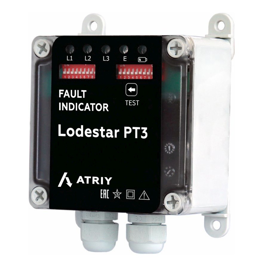

Lodestar PT3


Cable fault indicator Lodestar PT3 Technical specifications
| PARAMETER | VALUE |
| Mains voltage level, kV | 6-36 |
| Recorded fault types | |
| Identification of two-phase and three-phase faults | + |
| Identification of single-phase PtG | + |
| Determination of singlephase PtG direction | - |
| Fault detection on line switch-on (single-phase PtG, PtP) | PtG, PtP |
| Minimum zero-sequence current for single-phase PtG registration, А | up 10 |
| General description of devices | |
| Visual fault indication | LED indication |
| Power supply | |
| AC or DC supply voltage, V | 120/220 or ~220 |
| External backup power supply, V | - |
| Communication interface | RS-485 |
| Communication protocol | Modbus |
| Operation monitoring |
|
| Measurement accuracy | |
| Current, % | 5 |
| Mounting | |
| Mounting | switchboard mounting |
| External transducer | |
| Сurrent sensor | Rogowski coil, (3 pcs.) |
| Operating temperature range, °С | from –40 to +70 |
| IP rating of the indicator | IP 65 |
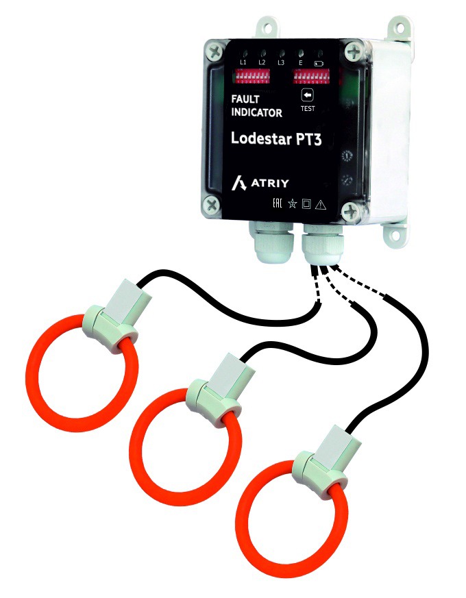
The fault indicator can operate in networks with insulated and resistance neutral. The cable fault detector is mounted in switchgear and control gear cell on the control board. The sensors of Lodestar PT3 fault indicator (based on the Rogowski coil) are mounted directly on cable phase conductors and transmit data to the indicator box.
Benefits:
- Fault type recording and classification – short‑circuit and earth fault recording with fault type discrimination.
- Faulted phase identification – indicates which phase is affected.
- SCADA integration – transmits fault information via configurable relay outputs or RS‑485.
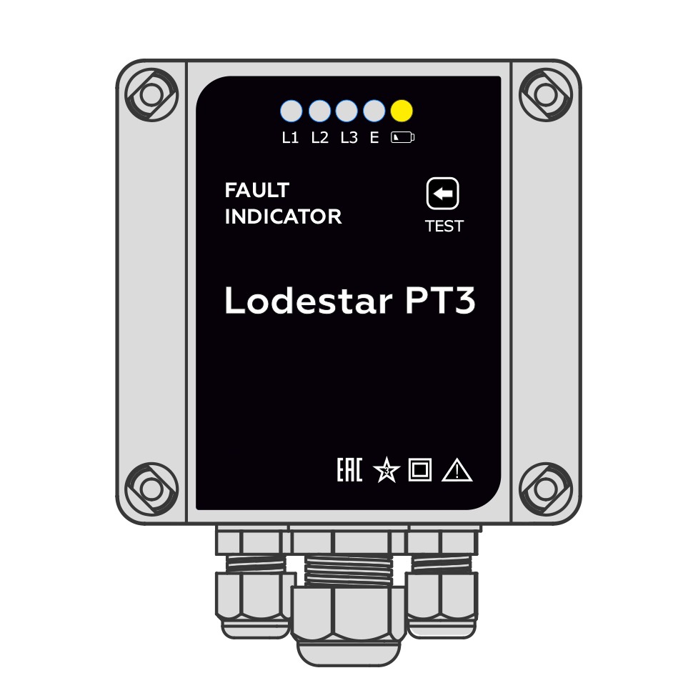
- Visual fault indication – dedicated LEDs for clear fault notification.
- Flexible power supply – 220 V DC, 110 V DC, or 220 V AC mains.
- Standby LED power – backup supply for fault indication during power loss.
- Battery monitoring – standby battery charge level indication.
- Adjustable setpoints – configuration via DIP switches or client software.
 Lodestar PT1
 Lodestar PT2
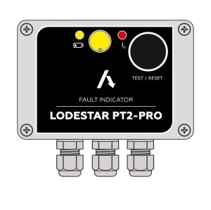 Lodestar PT2-PRO