

OLTC Controller UP-100
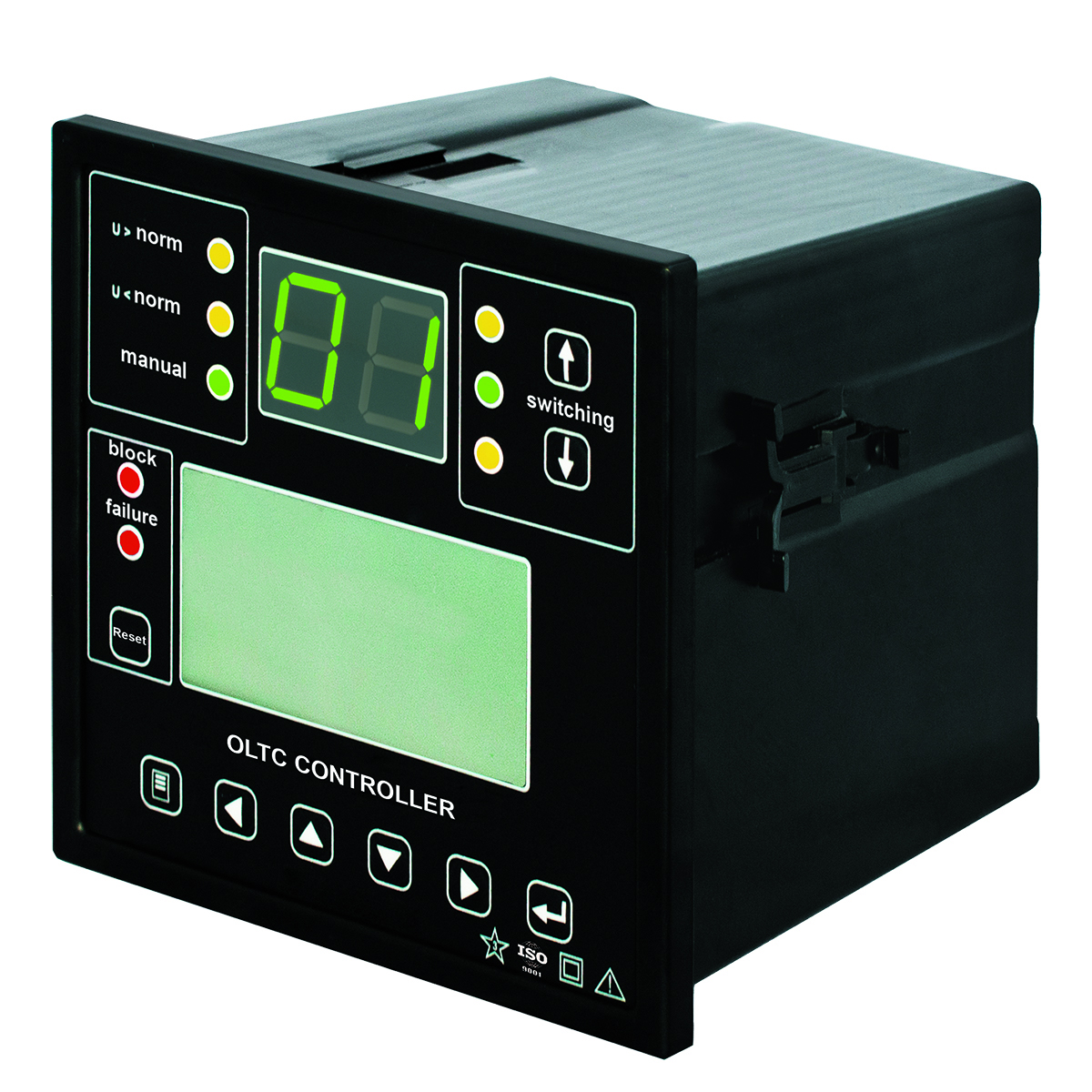
| PARAMETER | VALUE |
| Supply voltage | |
| Input AC voltage, V | 85 – 264 |
| Input DC voltage, V | 90 – 370 |
| Power consumption, no more than, W | 50 |
| Input analog signals | |
| Number of current inputs | 4 |
| Number of voltage inputs | 4 |
| Rated input AC, A | 5 (1) |
| Nominal input AC voltage, V | 100 |
| Input discrete signals | |
| Number of inputs, pcs. | 10 in UP 100/ 19 in UP 200 |
| Trip voltage | |
| When powered by DC, V | 150 – 260 |
| When powered by AC, V | 110 – 260 |
| Non-operating voltage | |
| When powered by DC, V | 0 – 130 |
| When powered by AC, V | 0 – 90 |
| Input signal duration (DC), ms | at least 50 |
| Output discrete signals | |
| Number of outputs | 7 |
| Maximum switching voltage of DC or AC, V | 260 |
| Switching current, A | 5 |
| Communication interfaces | |
| USB communication line interface | 1 |
| RS-485 interface, protocol – MODBUS | 1 in RE |
| TP analog output, mA | 0 – 20 |
| Indicator brightness, mcd | 10,000 |
| Degree of protection of the position monitor | IP 20 |
| Temperature range, °C | from – 40 to +50 |
| Warranty period, years | 5 |
| Service life, years | 15 |
UP 200 and UP 100 are the most compact OLTC position monitors for 36–750 kV substations. The panel version replaces LKM (Bulgaria), MR, MZ, and ED (Germany) type indicators. The monitors support automatic OLTC control under smooth or sharp load changes and are compatible with any existing position monitors and drives.
Compatibility with drives:
- MZ-2 and MZ-4 (Bulgaria);
- MR, EM and ED-S (Germany);
- RNT-13, PDP-1, PDP-4, etc. (Russia), equipped with BD404 or BD1404 selsyn sensors or with the replacement of the selsyn sensor with a DP-2 resistive drive position sensor or a DP-3 digital sensor with the “Current loop”;
- BUF3, BUE3 (Sweden);
- Huaming (China);
- any other drives with a resistive sensor or with a sensor with a “Current loop” output signal, or a BCD sensor with the number of stages not exceeding 99.
Benefits:
- Most compact design – smallest OLTC position monitor. It saves control panel space.
- Direct drop‑in replacement – replaces LKM, MR, MZ, and ED (Germany) type indicators.
- Wide voltage and current compatibility – connects to transformers with 100 V secondary voltage and 1 A or 5 A secondary current.
- Increased reliability – multiple increase in OLTC drive monitoring reliability.
- Enhanced diagnostics – adjustable control settings and emergency identification.
- Master‑slave operation – equalizes tap steps between drives.
- Freely programmable inputs – fully customizable configuration.
- Customizable outputs – distributed according to user needs.
- Large LCD display – displays multiple parameters simultaneously.
Functional features of the position monitors
- Automatic voltage maintenance within specified limits and correction of transformer voltage level according to load current.
- Measurement and indication of the current stage of the OLTC drive.
- Control and indication of current values of compensation voltage and current.
- Switching of OLTC drive positions by generating pulsed or continuous control commands.
- Control of command execution and serviceability of the OLTC switching device. Blocking of the OLTC drive in the event of:
- overload detection;
- detection of excess 3U0;
- voltage decreases below Umin;
- receipt of external relay blocking signals;
- emergency signaling in case of OLTC drive operation blocking.
- Quick changing of internal settings and operating mode (e.g., changing voltage maintenance settings from one value to another).
- Transfer of current parameters, input and change of settings via digital interfaces, USB/ RS-485 or analog “Current loop” interface to APCS or TM devices.
- Galvanic isolation of all inputs, outputs, and power supply circuits.
- Storage and viewing of information on the built-in LCD indicator.
- Collection, viewing, and transmission of up to 256 recorded events via communication lines.
- Real‑time event tracking with built‑in clock‑calendar.
Apabilities of oltc drive position monitors
- Continuous monitoring of the transformer switching device state.
- Regulator “input” operation with any type of OLTC drive position sensors – no additional adapters required.
- Regulator “output” operation with independent communication interfaces: RS‑485, Ethernet, and USB – enables easy automation of power equipment data regardless of year of manufacture.
- Easy operation for substation maintenance personnel – separate screens for displaying OLTC drive stage and monitoring current transformer operating parameters.
- Easy visual recognition of the current OLTC drive stage by substation personnel – 10,000 mcd bright indicators.
- Transfer of all information via modern communication channels to telemetry and SCADA systems.
- Combination of measurement, control and display functions in a single controller.
- Reliable voltage regulation – synchronization and parallel control of transformers in one or several groups.
- Control of up to 99 transformer drive stages with one regulator.
- High adjustment resolution (discreteness) of settings.
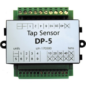 DP-5
DP-5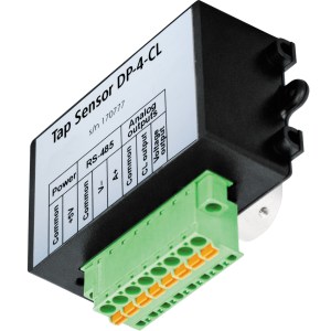 DP-4
DP-4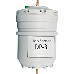 DP-3
DP-3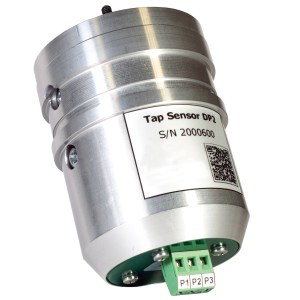 DP-2
DP-2