
FLISR software and hardware complex
| PARAMETER | VALUE |
| Voltage class of overhead and cable lines, kV | 6-36, 230 |
| Type of recorded faults |
|
| Minimum emergency current, А | 0.5 |
| Selectivity | determination of type and direction of fault |
| Ways of information processing |
|
| Registration |
|
| Temperature range, °С | from – 40 to + 85 |
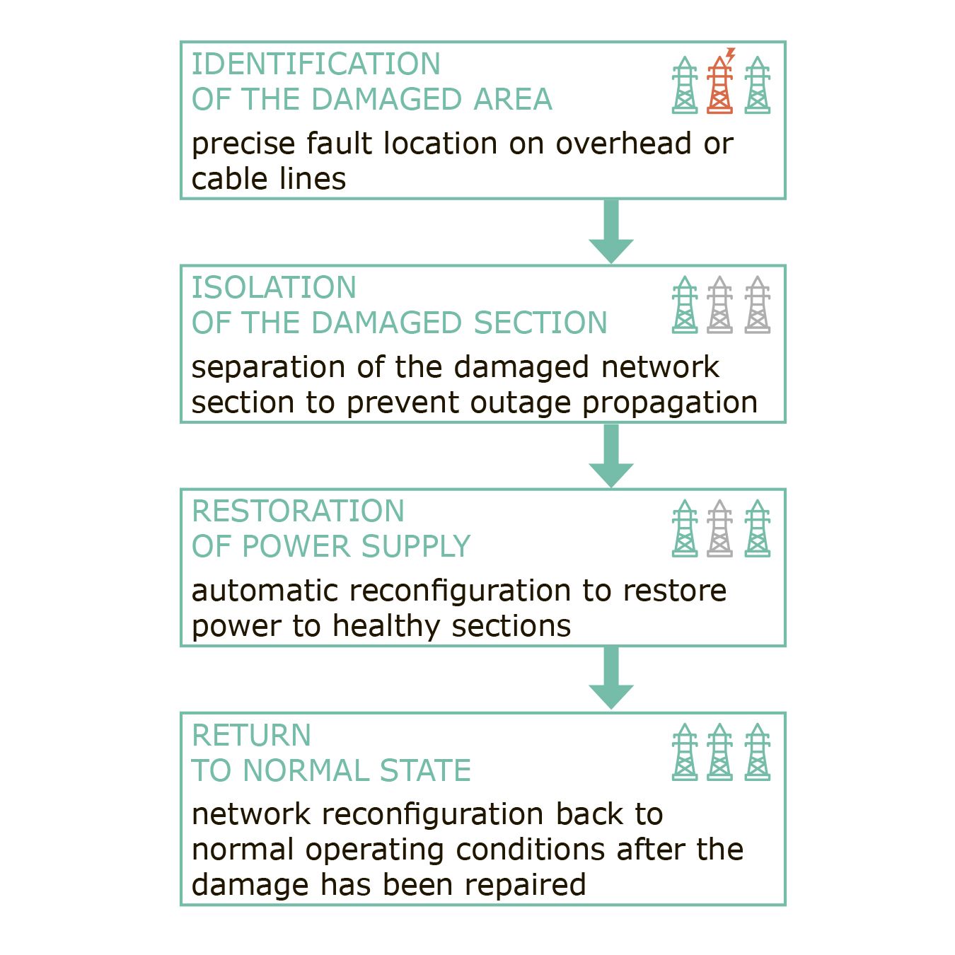
Designed for the implementation of FLISR technology in 6–110 kV distribution networks – determining the location of damage on overhead or cable power lines and isolating the damaged section to restore power supply to healthy sections of the network.
FLISR is effective in the following network configurations:
- cable (urban) networks with fully controlled switching devices in RM-6 units;
- on overhead lines with two-way power supply, in case of damage requiring the transfer of the normal current separation point;
- partitioning of long overhead lines achieved using multiple disconnectors.
Benefits:
- Minimum power timeout for consumers located in undamaged areas.
- Minimum of switching devices involved (no retrofitting of reclosers or switches in the power center for information transmission and remote control is required).
- All operations are carried out in automatic mode (except restoring normal power supply scheme – it is carried out in semi-automatic mode).
Features of FLISR Software and Hardware Complex:
- Any neutral type – operates in networks with any type of neutral grounding (isolated, solidly earthed, resistance earthed, or compensated).
- Any network topology – works in networks of any topology with one‑way or two‑way power supply.
- Any line type – works on overhead, cable, and overhead cable lines.
- Overhead line monitoring and control – remote control of overhead transmission line nodes via remotely controlled disconnectors and short‑circuit indicators with data transmission to SCADA.
- Substation observability – full visibility of each transformer and distribution substation using feeder monitors.
- Scalability – easily scalable system with the ability to expand both hardware and functional components.
ACTIVATION AND CONTROL
Activation of the damaged area separation algorithm in the FLISR Software and Hardware Complex is carried out with control of the command delivery time and prohibits other switching operations at the SCADA level. The system controls the execution and successful completion of the separation algorithm, recording changes in switching device position, voltage presence, current surges, and other relevant parameters. After power restoration following damage repair, the FLISR module of the monitoring and control system verifies the absence of overloads on the overhead line.
HARDWARE CONFIGURATION
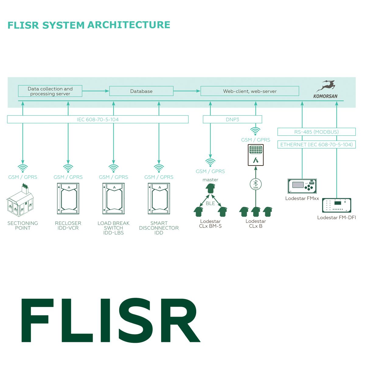
FLISR hardware depends on the network topology and existing equipment in the controlled area. The FLISR Software and Hardware Complex consists of:
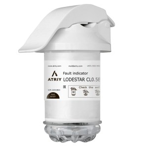
- wire‑mounted Fault Passage Indicators (FPIs) installed on overhead lines;
- pole‑mounted disconnectors and switches for overhead line sectioning;
- electrical network monitors installed in control panel cells.
All devices measure line parameters and transmit information to the system server and dispatch center via GSM or standard communication protocols. When processing information from FPIs, the system implements the fault location algorithm and issues a command to isolate the damaged area.
FLISR ALGORITHM
The FLISR algorithm is implemented during a long non‑current pause of the Software and Hardware Complex cycle, used on a switch in the power center or on a recloser installed on the main section of an overhead line.
ANALYTICAL MODULES
The analytical part of the system includes modules for:
- device visualization – displaying all system devices on a geographical map and mnemonic network diagram;
- fault analysis – determining the damaged area and accident location on the mnemonic diagram;
- partitioning options – providing configuration alternatives for network sectioning.
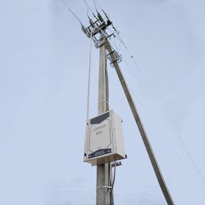 Smart disconnector IDD
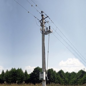 Load Break Switch IDD-LBC
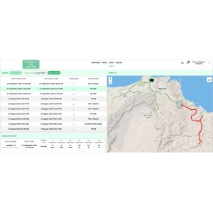 Monitoring and control system KOMORSAN
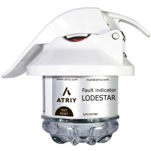 Lodestar CL0.5B
 Lodestar CL0.5 BM